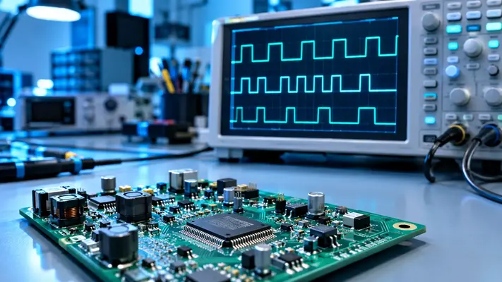
You’ve probably seen “DPWM” in a datasheet, a forum thread, or a chip’s block diagram and wondered if it was a typo. It isn’t. DPWM stands for Digital Pulse Width Modulation, and it quietly controls the power supply behind your laptop, phone charger, and LED lights.
Below you’ll get the plain-English DPWM meaning, how it works, and the one design trap that trips up beginners.
DPWM Meaning in Plain English
DPWM is a way of generating a pulse-width-modulated signal using digital logic instead of analog parts. A microcontroller, FPGA, or dedicated chip creates a square wave, and the width of each pulse sets how much power flows through a circuit.
A wide pulse delivers more energy. A narrow pulse delivers less. The percentage of time the signal stays “on” during each cycle is called the duty cycle.
Think of it like tapping a light switch very fast. If the light is on 70% of the time, your eyes see a bright bulb. DPWM does that switching with numbers and clock cycles instead of ramp voltages and comparators.
DPWM vs PWM: Is There a Real Difference?
The output signal looks the same, so the difference lies in how it’s made. Classic analog PWM compares a smooth ramp voltage against a control voltage. DPWM uses a digital counter and a digital duty-cycle value.
| Feature | Analog PWM | DPWM |
| Signal generation | Ramp + comparator | Counter + digital logic |
| Duty-cycle control | Voltage level | Binary number |
| Drift with temperature | Noticeable | Almost none |
| Reprogramming | Change components | Change firmware |
| Typical use | Legacy supplies | Modern digital converters |
The biggest win is flexibility. You can retune a digital power supply with a firmware update instead of a soldering iron.
How Digital Pulse Width Modulation Works
At its core, a DPWM block needs three things: a clock, a counter, and a duty-cycle command. The counter climbs from zero to a set maximum, then resets. That reset point defines one switching period.
The output flips to “on” at the start of each period. When the counter matches the duty-cycle number, the output flips to “off.” That’s the whole trick.
The Simple Counter-Comparator Method
This is the most common approach because it’s easy to build and easy to verify. The catch is speed. To get fine control, the counter needs a very fast clock.
The math is blunt: clock frequency = switching frequency × 2^N, where N is the number of bits of resolution. Double the resolution by one bit, and you double the clock speed you need.
Why Resolution Is the Real Battleground
Resolution decides how finely you can adjust the duty cycle. An 8-bit DPWM has 256 steps. A 12-bit one has 4,096 steps.
Coarse steps mean the output voltage can’t settle exactly where you want it. It hunts back and forth between two values instead. That behavior is called a limit cycle, and it’s the bug most DPWM designers fight.
DPWM Resolution vs Clock Speed: Real Numbers
Here’s what the counter method demands at a 500 kHz switching frequency, a common figure in compact DC-DC converters:
| Resolution | Duty steps | Required clock | Time per step |
| 8-bit | 256 | 128 MHz | about 7.8 ns |
| 10-bit | 1,024 | 512 MHz | about 1.95 ns |
| 12-bit | 4,096 | 2.048 GHz | about 0.49 ns |
Notice how quickly the numbers explode. A 2 GHz clock burns power and is hard to route on a chip. That’s why designers rarely push the pure counter method past 10 bits.
The takeaway: resolution isn’t free. Every extra bit costs speed, power, or silicon area.
Techniques That Beat the Clock Limit
Engineers have invented several workarounds. Each trades a bit of complexity for a big gain in resolution.
Delay-Line DPWM
A delay line chops one clock period into many tiny slices using a chain of gates. It gives excellent resolution but is sensitive to temperature and manufacturing variation. It’s popular in custom chips.
Hybrid DPWM
Hybrid designs combine a counter for the coarse part and a delay line for the fine part. You get high resolution without a gigahertz clock. Many commercial power controllers use this approach.
Dithering
Dithering rapidly alternates the duty cycle between two neighboring values. Averaged over time, the output behaves as if it had extra resolution. It’s cheap and effective, though it adds a small amount of ripple.
Where DPWM Is Used Today
DPWM sits inside far more products than most people realize. Anywhere a device needs efficient, precise power control, you’ll find it.
- DC-DC converters: Regulating voltage in laptops, servers, and phones.
- Motor drives: Controlling speed in drones, fans, and electric vehicles.
- LED drivers: Dimming lights without flicker.
- Solar inverters: Squeezing more energy out of panels.
- Class-D audio amplifiers: Turning digital audio into speaker power efficiently.
DPWM in FPGA Designs
An FPGA is a popular playground for DPWM. Designers can code a counter-based block in a few dozen lines of hardware description language. Modern FPGAs also include dedicated clock-management tools that make hybrid DPWM practical for prototypes.
The Mistake That Ruins Digital Power Supplies
Here’s the trap. Suppose your analog-to-digital converter (ADC) measures output voltage in steps of 10 millivolts. Your DPWM, meanwhile, can adjust the output in steps of 2 millivolts.
The controller sees a “flat” reading but keeps nudging the duty cycle, because its output is finer than what it can measure. The result is a steady, annoying oscillation.
The fix is a well-known design rule: make the DPWM resolution finer than the ADC resolution. The controller then has room to settle on a value the ADC reads as constant.
Practical Tips Before You Design One
A few lessons from real projects will save you weeks of debugging.
- Start from your ADC. Decide its step size first, then pick a DPWM resolution that beats it.
- Budget your clock. Check the power cost of your target frequency before committing to a 12-bit counter design.
- Simulate the loop, not just the block. A DPWM that looks perfect alone can still cause limit cycles in a closed loop.
- Consider hybrid early. Retrofitting it later is painful.
Final Verdict
The DPWM meaning is simple: digital pulse width modulation, the digital brain behind efficient power control. The real skill lies in balancing resolution, clock speed, and your ADC.
Here’s the insider tip worth remembering. Before chasing more bits, check whether your feedback path can even see the improvement. If it can’t, extra resolution is just expensive noise.